

Whether it’s a dredging operation or a cooling water process, the work goes on, day and night, worldwide. Lagersmit introduces the next step in ensuring a stable pump operation. With the specially selected digital flow meters, the monitoring of the seal and thus of the pump condition becomes very easy. We would like to explain how it works!
The benefits summarised
- It is easy to monitor the condition of the seal
- With two flow meters you can monitor whether the pressure of the flushing pump needs to be adjusted
- Maintenance can be planned
- Maintenance intervals are maximised
- Sudden pump failure is prevented
- The costs are reduced to a minimum because unnecessary maintenance is avoided
- The flow meter provides better control and accuracy of flush measurement
- The flow meter can be applied on all Liquidyne seals
From buckets to digitally measuring the condition of the seal
In a previous blog we explained how to measure the condition of the seal manually. It’s a regularly recurring task which delivers you valuable information, but still takes some time and effort. In addition, a ship is not always stable and the pump may not always be accessed easily. This method leaves room for improvement, because these ‘bucket and stopwatch’ measurements are less exact than digital seal measurements.
The digital flow meter makes the whole process both easier and more exact! Find out next which benefits this offers you.
How to monitor the condition of the seal with the flow meter
A flow meter is used to measure the rate of flow of liquids, in this case water. For Liquidyne pumping applications, Lagersmit has carefully selected and tested a number of flow meters. The flow meters that passed the final tests are fully digital. By installing the non-mechanical flow meter in a pipeline from the pump, the flow is logged without disrupting the flow. The data can be logged in your data management system or locally at the pump site. If logged, you will see a similar graph to Figure 1.
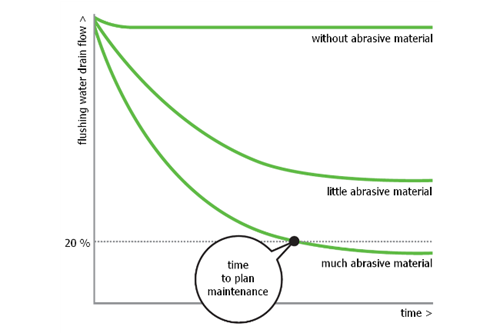
Figure 1: Condition Monitoring
The state of the grooved bush is measured based on the flow. Due to the wear of the grooves on the grooved bush, the flow decreases over time. The grooves are flattened and the lip seal will have more contact with the running surface. This allows less water to be transported over the bush. The water flow towards the drain decreases, and as a result the drain flow decreases. If this drain flow is down to 20% of the initial flow, maintenance is required.
Application flow meter
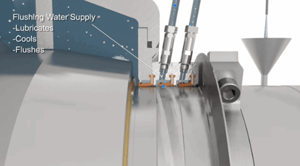
The flow meter can be applied in two ways. Figure 2 shows two pipelines. The left one is the flush-in (supply) and the right one is the drain-out. It is possible to place the flow meter on the drain-out, or on both pipelines. By monitoring the drain-out only, you are able to carefully monitor the flow up to the point where maintenance is needed. However, by also monitoring the flush-in flow, you are able to fine-tune the flush-in flow which in turn will lead to better sealing results and a longer seal lifetime. Combining the two measurements will give you even more accurate figures on the functioning of the Liquidyne.
Alternative 1: Flow meter on the drain-out
A flow meter can be installed on the drain-out and by doing so you can log the drain flow. You can now follow the performance of your Liquidyne and flushing capacity without the need for manually checking the drain flow. This drain-out flow reduces in time due to the grooves being worn down. Flatter and worn-down grooves means less lubrication and less draining while sealing your pump. By logging the start drain flow and monitoring the flow development over time, maintenance can be planned.
Alternative 2: Placing flow meters on both pipelines
The flow meter may also be placed on two pipes. We will explain why. The water is pumped from the left-hand pipeline to the right-hand pipeline. This is illustrated in Figure 2. When the pressure in the left-hand pipeline is higher than in the pump, some water is flushed into the pump keeping the seal clean.
By placing two flow meters you don’t only measure how much water is transported through the Liquidyne and thus whether the grooved bush wears down, but also how much water flushes into the pump. It is of course intended that most of the water is pumped through the Liquidyne. With two flow meters you can find out whether the pressure of the pump needs to be adjusted to flush more efficiently.

Figure 2: Flushing water supply
Suitable for which Liquidyne seals?
The digital flow meter can be applied on all Liquidyne seals. This means you can apply the flow meters on dredge pumps, industrial (cooling) water pumps, jet pumps, gland pumps and process pumps. The Liquidyne 3-stage is used as an example, but the flow meter is also applicable to all the other Liquidyne types. Find out which Liquidyne seal best fits your pumping application by clicking the link below.
Type of flow meter for dredging and industry
The choice for the type of flow meter depends on the operational pressure. In general our advice for dredging seals is a flow meter capable of withstanding high pressures, and for the industry a flow meter that can withstand working pressures up to 16 bar. At low pressures a flow meter up to 16 bar is also possible for dredge seals.
Our experts have made a careful selection of suitable flow meters, contact us for more information.